Vehicle Centre of Gravity
It all starts with a definition
Locating the Center of Gravity (CG) in three dimensions (length, width and height) is an important first step to analysing many aspects of a vehicles performance, especially the suspension characteristics. For instance, the length and height dimensions are important when analyzing anti-dive and anti-squat suspension geometry.
In this article I’m going to try to explain the “Math” by deriving the main equations. For those of us who are challenged to remember back as far as high school or first year college math and Physics, don’t worry, although I use some trigonometry functions to derive the formulas, the end result uses “real” measurable numbers.
In order to calculate the length and width dimensions of the CG, the vehicle will need to be weighed on a flat level surface. Usually this entails measuring the weight at each wheel by placing a scale under each. Be careful when lowering the wheels onto the scales, so as not to push the scale sideways. If this does happen you risk causing the mechanism to bind which may result in a false reading. Commercial scales for measuring the corner weights of race cars are available that allow the vehicle to be driven onto the scales thus avoiding this concern.
Note: you might consider looking around at the local performance car clubs. These clubs will often have invested in a set of scales for members to use. Shops that setup race cars or performance street suspensions may also have a set of scales.
To find the height dimension of the CG, the vehicle will need to be safely raised (as high as possible) at one end and the weight under each wheel again measured while in the raised position. To avoid the previously identified scale binding concern, the rear wheels are often easiest to lift, especially if the vehicle is equipped with a solid rear axle. My formula’s assume that the rear has been lifted.
With reference to the various figures, we need to first measure the values of the following variables:
|
Variable |
Description |
|
Dwb |
Wheel Base - measures the distance between front and rear wheel centres. This can be accomplished by suspending a plumb bob from the centre of a front and rear axle on the same side of the vehicle and measuring between the suspended strings. |
|
Dtkf |
Front Track - measures the distance between the centres of the front tyre ground contact patches. |
|
Dtkr |
Rear Track - measures the distance between the centres of the rear tyre ground contact patches. |
|
|
|
|
Wfl |
Weight under the front left wheel ( with vehicle on level ground ) |
|
Wfr |
Weight under the front right wheel ( with vehicle on level ground ) |
|
Wrl |
Weight under the rear left wheel ( with vehicle on level ground ) |
|
Wrr |
Weight under the rear right wheel ( with vehicle on level ground ) |
|
|
|
|
Dup |
The height that both rear wheels are lifted off the ground. For convenience and accuracy, this should be measured between the rear wheel centre and the ground. Usually a lift height of 12-16 inches is the maximum necessary to achieve usable results. |
|
Dwbup |
Wheel Base lifted - measures the horizontal distance between front and rear wheel centres once the vehicle is lifted by height of Dup. Dwbup should in all cases be less than Dwb. The measurement can be accomplished in the same way as before, by suspending a plumb bob from the centre of a front and rear axle on the same side of the vehicle and measuring between the suspended strings. |
|
|
|
|
Wflup |
Weight under the front left wheel ( after lifting the rear wheels by height Dup ) |
|
Wfrup |
Weight under the front right wheel ( after lifting the rear wheels by height Dup ) |
|
Wrlup |
Weight under the rear left wheel ( after lifting the rear wheels by height Dup ) |
|
Wrrup |
Weight under the rear right wheel ( after lifting the rear wheels by height Dup ) |
|
|
|
|
Dwr |
Distance of the centre of the axle to the ground, when all four wheels are sitting level on the ground. |
|
|
|
Table
Length Dimension
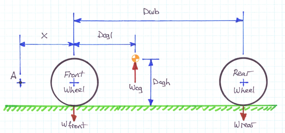
With reference to the side view of Figure 1, we can see that the distance Dcgl defines the length co-ordinate of that imaginary point where the total weight of the vehicle would balance front to rear.
Figure 1
If we take a point A some distance X in front of the vehicle we find the moment equation for that point is described by:
(X + Dcgl) * Wtotal
Looking at the diagram we can see that the following conditions hold:
Wfront = Wfl + Wfr
Wrear = Wrl + Wrr
Wtotal = Wcg = Wfront + Wrear
Substituting variables and generating a balanced equation of moments we get:
( X + Dcgl) * Wtotal = (X * Wfront) + ((X + Dwb) * Wrear)
If we now define X = 0, the front wheel axle centre becomes the pivot point. Substituting for Wtotal and solving for Wcgl we derive our first equation:
|
Equation 1: |
Dcgl = |
Dwb * Wrear |
|
|
|
Wfront + Wrear |
Width Dimension
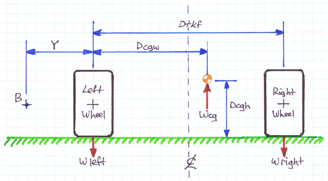
Figure 2
Looking at the rear view of figure 2 we can see that the following conditions hold:
Wleft = Wfl + Wrl
Wright = Wfr + Wrr
Wtotal = Wcg = Wleft + Wright
By the same reasoning used to derive equation 1, we see that we can generate an equation of moments about the point B as follows:
(Y + Dcgw) * Wtotal = (Y * Wleft) + ((Y + Dtkf) * Wright)
As before if we take Y=0, the left wheels become the pivot point. Substituting for Wtotal and solving for Dcgw we derive our second equation:
|
Equation 2: |
Dcgw = |
Dtkf * Wright |
|
|
|
Wleft + Wright |
Using these two equations together, we see in the top view of figure 3, how the co-ordinates relate to each other.
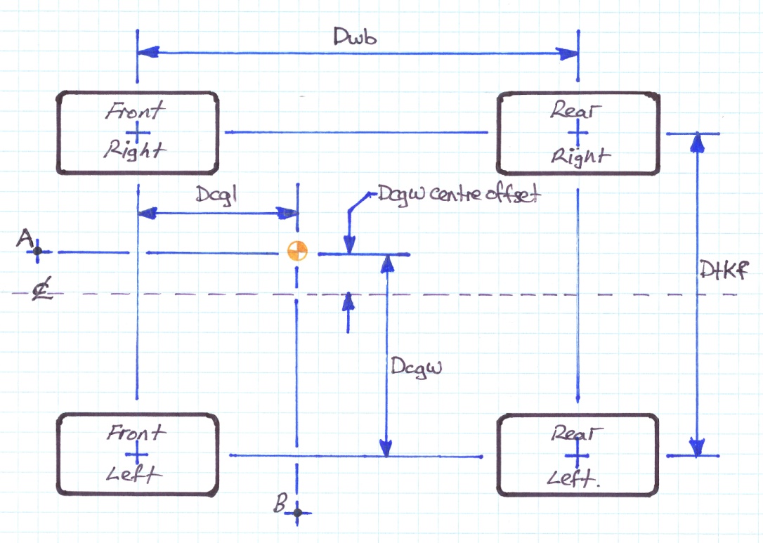
Figure 3
From a practical measurement perspective it may be easier to find the centreline of the vehicle and measure an offset in the transverse direction. This can be done by calculating DcgwCentreOffset as follows:
|
Equation 3: |
DcgwCentreOffset = |
Dcgw – ( Dtkf / 2 ) |
|
|
|
|
Notes:
If the result is negative we measure left of the longitudinal centre line. A positive result is measured to the right of the Longitudinal centre line as drawn in figure 3.
In this case I’ve specified the front and rear tracks to be equal. This is rarely the case and normally the track at one end of the car is a little wider than the other.
Figure 4
Figure 4 shows how a wider rear track effects the calculations. You can see that the additional rear width can be described using two similar triangles of angle theta, where the opposite sides represent the additional width with adjacent side lengths Dcgl ( ie. T1 ) and Dwb ( ie. T2 )as follows:
Tan ( theta ) = ( T1 / Dcgl ) = ( T2 / Dwb )
We also know that T2 = ( Dtkr – Dtkf ) / 2
Substituting T2 and solving for T1 we produce:
|
Equation 4: |
T1 = |
Dcgl * |
( Dtkr – Dtkf ) |
|
|
|
|
|
2 * Dwb |
|
DcgwCentreOffset now becomes:
|
Equation 5: |
DcgwCentreOffset = |
Dcgw – T1 – ( Dtkf / 2 ) |
|
|
|
|
Note that if the front and rear tracks are the same width, T1 goes to zero and equation 5 reverts to its previous form as shown in equation 3.
Height Dimension
This one is a little more complicated, but the way it is calculated has been around for years and once you see how it is done, I think you’ll agree that the reasoning is rather clever. Essentially, we assume that the vehicle is a solid object and that the CG doesn’t move, within that object. This is true regardless of the objects orientation. If we refer back to Figure 1 & 2, we see that the location of the CG is not only defined by variables in the length (i.e. Dcgl) and width (i.e. Dcgw), but also in height (i.e. Dcgh).
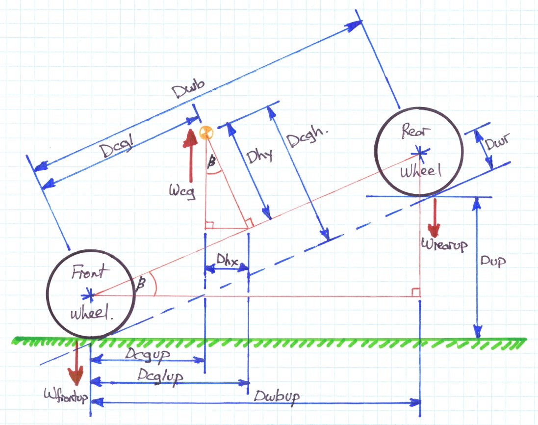
Figure 5
To find the height of the CG, we need to lift one end of the car (in this case the rear) and weigh all four wheels again using the same scales as before. For best results it is necessary to immobilize the suspension so that the springs do not compress. Spring compression changes the relationship of the wheel to the body and therefore also the CG. By substituting the new weight measurements, we can find the “new” horizontal dimension of the CG (ie. Dcgup) and produce the following equation:
|
Equation 6: |
Dcgup = |
Dwbup * Wrearup |
|
|
|
Wfrontup + Wrearup |
Using the same reasoning that was applied to the derivation of equation 1, we know that the following definitions hold:
Wfrontup = Wflup + Wfrup
Wrearup = Wrlup + Wrrup
Using similar triangles we know that the triangle with hypotenuse = Dwb and Adjacent side = Dwbup is similar to the triangle with hypotenuse = Dcgh and Opposite side = Dhx and the triangle with Hypotenuse = Dcgl and Adjacent side = Dcglup. For each triangle, the angle shown as Beta is also equal.
Looking at the diagram, we can see that the following conditions hold:
Dcgh = Dhy + Dwr
Dhx = Dcglup - Dcgup
Sin( Beta ) = Dhx / Dhy => Dhy = Dhx / Sin( Beta )
Cos( Beta ) = Dcglup / Dcgl => Dcglup = Dcgl * Cos( Beta )
Substituting and simplifying:
Dcgh = (( Dcglup – Dcgup ) / Sin( Beta ) + Dwr
Dcgh = (( Dcgl * Cos( Beta )) /Sin( Beta ) ) – ( Dcgup / Sin( Beta )) + Dwr
Dcgh = ( Dcgl / Tan( Beta ) ) – ( Dcgup / Sin( Beta ) ) + Dwr
Furthermore we know that:
Sin( Beta ) = Dup / Dwb
Tan( Beta ) = Dup / Dwbup
Substituting further:
Dcgh = (( Dcgl * Dwbup ) / Dup ) – (( Dcgup * Dwb ) / Dup ) + Dwr
Finally, substituting into equation 6 and simplifying a little we derive the final equation:
|
Equation 7: |
Dcgh = |
( Dcgl * Dwbup ) |
+ |
(( Dwbup * Wrearup ) * Dwb ) |
+ Dwr |
|
|
|
Dup |
|
( Dup * ( Wfrontup + Wrearup ) ) |
|
Conclusion
There you have it. By plugging a number of relatively simple measurements into the three main equations ( 1, 2 & 7 ), we can determine ( in theory ) the exact location of the CG of any four wheeled vehicle.
Author: Mark Elbers
Disclaimer: I’m not an engineer, just a guy with access to relevant technical documentation and a sense of curiosity. This article presents my thoughts, based on the research and general reading that I’ve performed on this topic. If you find errors in my work I would appreciate hearing from you. I can be contacted through the WWWEDGE e-mail list (tr8@mercury.lcs.mit.edu).