Triumph Stag Maintenance
to add your tips send an email to jell
this page updated 24-Oct-01
Overview
Differences MKI vs MKII (by Peter Howells) and (by Glenn Merrell)
Remember that Mark I and Mark II are not "Official" Triumph or British Leyland
designations. This is why the hazy differences between what we have all come to
know as Mark I and Mark II. Most assume that there is a clear dividing line
between chassis/engine numbers and Mark I / Mark II features, where there is
actually not. Infact modifications were built in on an availability or stock base.
The main differences that are obvious are
MkI has
Chassis number less than LD20,000
- No coach trim line
- Grey background to leaping stags on badges
- Steel or wire wheels
- No quarter lights in hood (or sixth lights as they are now called)
- Interior lights in B posts
- Big 16inch Steering Wheel
- Matt Black surrounds to instruments with needles pivoting from tops of gauges
- Map reading lamp in glove box lid
- Rear Number plate lights in bumper bar
- Front Seats have 9 strips of basketweave, Mk2 have ten.
- No delay on wipers
- Door Mirrors
MkII has
Chassis after LD20,000
- Hazard Switch comes in at 20000
- Seat belt sign comes in at 38000
- Door mechanisms Mk2 start at 21800 (20800 USA
Not all the above is on all Mk1, as we have a hybrid often called 1 and a
half, even after chassis 20000. Which leaves the question, where does the full Mk2 start?
There are lots of other differences which are not immediately obvious, under
the bonnet etc.
Sometimes Mk1 owners, as I am, have to fit Mk2 parts because the Mark one
stuff is not available.
My last example of that is Steering rack. Mk1 original was 4+ turns lock to
lock. Mk2 is only 2+half.
Peter Howells
Stag Cooling (by Glenn Merrell, 73 Stag)
Since lately I have been studying the cooling system of the original
Stag engine, the generally accepted methods of maintaining
cooling on a Stag that I've found are:
- have the radiator recored to a 3 or 5 row core or modified cross
flow;
- make sure the original style thermostat with blanking disk is used on
a Mark II induction manifold designed with a bypass hole in the back of
the manifold. CAUTION - If you have an early Mark I manifold that does
not have a bypass hole behind the thermostat hold, DO NOT use a
blanking disk style thermostat as it may NOT OPEN. This is due to the
fact that the shaft of the thermostat has no place to travel when
opening, where in Mark II induction manifolds, the blanking disk shaft
travels into the bypass hole when opening;
- retorque the intake manifold and cylinder heads every 3000 miles,
6000 miles maximum;
- pressure flush the cooling system once a year, replacing the
antifreeze coolant with new;
- rod out the radiator every two years, or with #4;
- use only original style molded reinforced hoses;
- se only a 20 psi radiator cap on a Mark II, 13 psi cap on a Mark I;
- properly bleed the air out of the system.
From the previous research and articles I've read, most folks seem
problem free with the Stag cooling.
Adequate Maintenance:
It appears that only systems that have not been maintained, or not had a
quality engine flush to remove the engine block sediments are actually
having problems (I found about an inch or so of crud my engine block
when disassembled). My nose is tuned to the smell of antifreeze, and I
panic when I smell it. Most of the time it is a passing car with a
leak, but I always check it out.
Six vs. Twelve Vane water pump impellers:
The reports of the 6 to 12 vane pump impeller swap increasing cooling I
would be suspect of, without first performing all the generally accepted
maintenance and modifications first.
Racing use:
If any use of the Stag engine would cause a problem in the cooling, I
would think it would be racing. Hart Racing recommend
refitting of a higher capacity radiator. The information on cooling
from Hart that I have read, and since Hart races Stags professionally, I
would take their advice for cooling system maintenance. Removing the
heat from the engine compartment through exhaust modifications should
help also, which I bet that none of the racing engines at Hart have
other than tubular exhaust manifolds.
Cylinder head gaskets:
I've also noted several different types of cylinder head gaskets. I do
not know the manufacturer of each, but one style I've seen does not have
hole openings that match the water jacket's semi circular holes in the
block and cylinder heads. Where there is a semi circular opening in the
metal, there is only a small round hole in the head gasket. The intake
manifold gaskets also have a smaller hole than the hole for water flow
from intake manifold to the cylinder head. These restrictions would
impead the flow of water through the water jacket, causing less heat
removal.
Engine Block casting problems:
On one block, the water passage leading to the water pump suction on
one side had some casting flash bent up obstructing the pump suction by
about one-half. I've read other reports of this problem.
System Filling, air bleeding:
Since the high points that can trap air in the system are in the heater
coil and intake manifold, jacking the front of the car to cause the air
to find its way out should be done over a period of time while at idle,
and topping off the radiator. An air bubble in the wrong place in the
cooling system could possibly interrupt flow on one side of the engine,
and cause overheating or over pressure.
Summary:
To date, I think the above is a summary of what has been done by just
about everyone who has owned a Stag. It only takes one time to overheat
and rupture a head gasket or warp the cylinder head. From what I have
read, the cause leading to the overheat was lack of proper maintenance.
The best recommendation so far is...regular periodic maintenance.
Who knows what I will come up with down the road, maybe only to verify
that the general maintenance works fine.
Regards,
Glenn Merrell, 73 MarkII Stag (in surgery)
Annual Cooling System Flushing (by Glenn Merrell, 73 Stag)
When preparing to perform the annual flush of the cooling system,
obtain a good quality flushing detergent. Make sure it states that it
is not harmful to aluminum, and ones with corrosion inhibitors seem to
work the best.
Prestone has a two part flush powder - one half is
detergent for the flush, the second part is corrosion/rust inhibitor
used in the rinse flush.
First disconnect the heater core from the flushing
by removing the feed and return hoses. Reverse flush it later by using
a cut off garden hose attached to the heater return port (normally
connected to a pipe that runs to the water pump cover) and connect a
length of hose to the supply side of the heater core (normally connected
to the left hand head) and route it into a drain.
Reconnect the two
engine side heater hoses using a suitable length of copper tubing, or if using
a power flush connection, this is a good place to connect the tap. This
bypass of the heater core will keep you from depositing the crud from
the engine and cooling system right into your heater core. (You would only
notice this when the weather turns colder and you were wondering why the
heater does not work, as you panic to think that the cooling system has
gone too.)
Drain the cooling system and radiator by removing the lower
hose on the radiator, disposing of the coolant properly. Remove the
thermostat and reinstall the "water elbow" or "gooseneck". Follow the
directions for flushing the system, being careful not to boilover or
overheat the heads. If using a power flush system using the garden hose,
make sure that the water is on for the whole engine flush cycle. Never
pour cold water into a hot engine, as you will surely warp the cylinder
heads and possibly crack the block.
While the cooling system is flushing,
take a good look at the thermostat. If is is clean and tidy, test the
thermostat by placing it in a sauce pan of water and bring it to a
simmer on the stove. Use your wife's candy thermometer (you do this when she
is out shopping, of course) to observe the temperature when the thermostat
opens, and make sure the thermostat opens. It should open fully, and if
the boil is not too agressive, it is a kick to watch it open and close
for the first time. After verifying that the thermostat opened at the
proper temperature, remove it from the burner and add cold water to the
pan to slowly cool the water. Observe that the thermostat closes. If
the thermostat is dirty, or does not fully open or close, discard it
and buy a new one with a new gasket. Most are less than 5 pounds
sterling or $8 US, which is somewhat less costly than replacing a burst hose on
an outing, or, the cylinder heads and gaskets.
By now the flush has progressed nicely and your neighbors are wondering
why there is a steaming river running through the development. Shut down
the engine, allowing the engine to cool normally. You will find that the
garden hose kept the engine from heating past one quarter on the gauge
(now just how long is that hose, anyway?). Now is a good time to flush
the heater core as described above. After flushing, reconnect the
heater core to the supply and return lines, open all drain taps to drain out
the flush and making sure that the taps are clear and flowing, repeat with
fresh water if necessary.
Replace the thermostat and gasket, carefully
positioning the jiggle pin or bleed hole at the 12:00 o'clock position.
Replace and tighten the drain taps in the block, and tighten all the
hose clamps. When the engine is just warm to the touch, refill the
system with a mix of 50/50 destilled water/antifreeze. Use antifreezes
that have corrosion inhibitors. I have found that the environmentally
friendly antifreezes do not last more than 6 months, and eat your
engine.
Regards
Glenn Merrell, 73 Mark II Stag
Cylinder Head Removal (by Glenn Merrell: 73 Stag)
The Rope Method:
Preface: The intent of using this method is to remove a stuck cylinder
head. Suspending the vehicle on the engine pulling tabs will only stress
other components; wedges will trash the cylinder head beyond repair; and the
head pulling bracket may not work in all occurrences.
I have used this method on several engines, one with all five studs seized, and in all cases, the heads lifted about +1 inch, enough room to jab saw the studs up close to the head. Also in all cases, no connecting rods were bent.
Depending on the reason you are removing the heads, it would be wise to pull the tappet buckets and pallets to see if any valves are bent. If so, expect to find a broken valve in the cylinder, and do not crank the engine without a length of rope in the cylinder. Otherwise, the valve piece will imbed itself into the soft aluminum once for each rotation, and most likely trash your head.
Do not bother trying to soak the studs, the penetrant never goes more than
1/2 inch past the surface, no matter what the claim of the penetrant. But,
if it makes you feel good, go ahead and spray away, the runoff will help
loosen the grease cake on the side of the engine. Also, DO NOT attempt to
weld anything onto the broken off stud(s), it will only damage the bolting
washer surface which needs to be perpendicular to the stud axis. It would
be a good idea to view Tony Hart's timing chain video first, available from
Tony Hart, the SOC, or Rimmers. Tony does not stock US formats of the
video.
Materials needed:
- a lot of patience, but hell, you have tried every method known to man
already, so push on;
- normal automotive hand tools;
- gear puller;
- a stud extractor/vice grips with GOOD jaws;
- 8 to 12 feet of 3/8" braided nylon rope;
- a working starter;
- a charged battery;
- a battery charger;
- spray lube oil/penetrant like WD40 or equivalent;
- long thin screwdriver or 1/4 inch wooden dowel;
- a remote hand start button (not necessary, but keeps you from running back
and forth to the ignition key);
- a hand jab saw...I do not recommend using a power saw, as you can severely
damage your head beyond repair. A little patience and elbow grease using a
hand jab saw and good quality blade, renewing the blade as necessary, will
save you the grief from realizing that you went through all this trouble
just to trash a head. A jab saw is a hack saw/metal saw with no holder on
one end of the blade;
- a 1/4 inch drift pin, or tapered drift pin;
- a 10 pound hand mallet;
- about 4 hours of patience and labor;
- a sauna or hot tub, several pints of your favorite brew (for use
afterwards)
Initial Procedure: (basically, remove everything from the engine)
- pull fuses for the fuel pump, and all electrical accessories
- drain radiator and engine block
- remove intake manifold, power steering pump, A/C bracket, radiator, fan,
torquatrol;
- Turn crank to TDC #2, remove harmonic balancer using a gear puller;
- remove timing chain cover, timing chains, mark crankshaft and jack shaft
positions on the block, remove cams, spark plugs;
- remove all cylinder head studs and nuts that can be removed;
- disconnect hoses and electrical connections from rear of cylinder heads;
- replace the harmonic balancer onto the crankshaft, without the center bolt;
- spray a penetrant oil into each cylinder, hand cranking the engine as
necessary to get the cylinder bores lubricated-if you have an air hammer, it
would be a good idea to air hammer the studs, as this helps break them free
from the cylinder head.
Overview:
The basic idea using this method is to use the power of the starter to
move the piston at velocity, compressing the nylon rope against the cylinder
head. Not to worry, combustion explosion in the cylinder exceeds 2000 psi.
This compression, when repeated several dozen times, will break the stud
free enough to lift the cylinder head about one inch. The sequence to be
followed is open to the user, but I have found it best to start with the
front cylinder and work my way back until I see how the head is lifting. If
some studs are giving you a particularly hard time, concentrate on the
cylinders on either side of the stuck studs. RESIST ALL TEMPTATIONS TO USE
A PRY BAR AND WEDGES.
Removal Procedure:
- with one hand, place the long screwdriver or dowel into the spark plug
hole of the stuck head;
- rotate the crank counter clockwise (CCW) with the other hand until the
piston is at the bottom of its stroke, using the dowel as an indicator;
- remove the screwdriver and carefully feed the nylon rope into the
cylinder through the spark plug hole, leaving a loop exposed to remove the
rope...DO NOT INSERT ALL OF THE ROPE INTO THE CYLINDER, AS YOU MAY NOT BE
ABLE TO RETRIEVE IT!!!;
- rotate the crank by hand to compress the rope in the opposite direction
(CCW) from the normal rotation. Tick over the engine using the starter.
RELEASE THE KEY/REMOTE BUTTON AS SOON AS THE crankshaft STOPS ROTATION, OR
YOU WILL BURN OUT YOUR STARTER. The engine rotation sill stop with a dull
thud. The starter is not strong enough to push the head up with normal
rotation. It needs the counter rotation to bet enough momentum to strike
the head with the rope in the cylinder
- Rotate the crankshaft CCW in the full opposite direction by hand to
compress the rope in the opposite rotation:
- tick over the engine using the starter, again releasing as soon as the
crankshaft stops rotation;
- rotate the crankshaft CCW to the bottom of its stroke, feed in more rope
if necessary (you will know if it is necessary if the engine cranks several
full rotations);
- rotate the crankshaft CCW by hand to compress the rope in the opposite
direction;
- tick over the engine using the starter, again releasing as soon as the
crankshaft stops its rotation:
- REPEAT steps 5-9 until you see some movement of the cylinder head,
which may be 10-20 times, then;
- rotate the crank CCW to loosen the rope, remove the rope from the
cylinder, move to the next cylinder, start at step #1;
- when the head has lifted to a distance of about one inch, move the
cylinder head gasket up against the bottom of the cylinder head. This is to
insulate the head from the jab saw;
- carefully, jab saw the stud as close as possible to the head, being
careful not to contact the head;. This will give you a one inch stud to
grab with a stud extractor or vice grips.
The fun part...
- support the cylinder head on some wood blocks;
- drive the head studs out of the head with the drift pin and 10 pound
mallet (ohhh..yes, this feels soo good, wear some good gloves and goggles)
- repeat for second cylinder head
- go sit in the sauna, drink a beer.
Regards,
Glenn Merrell
Keep Your Stag Cool, Install a NEW Composite Cowl Today
Cylinder Head Fastening (by Glenn Merrell: 73 Stag)
A On the Stag engine, the cylinder head studs are not perpendicular to
the block, where the head bolts are perpendicular to the block.
Expansion and contraction forces are not equal on the lower threads that
penetrate into the block to the upper stud threads. There are 8 threads
into the block on the stud fully inserted, but only 3.5 threads engaging
the upper stud by the head nut. There is more force per square inch
taken up on the nut thread area than than distributed across the threads
into the block; that is, assuming similar force on top and bottom parts
of the stud (which is actually different because of the diagonal
insertion into the block at the bottom), the bottom of the stud has a
larger thread surface contact to spread out the force, the upper stud
has less thread area by more than a 2.2:1 ratio bottom threads to top.
The nut takes more than two times the force due to less area.
B The cylinder block is cast iron, the cylinder head is cast
aluminum. The cylinder head studs are hardened steel. From my basic
physics, I recall that aluminum expands something like 3:1 to steel for
the same heat applied, and contracts in the same ratio. Every time the
engine goes through a heat/cool cycle, the expansion/contraction
dynamics occur on all of the components. The studs, threads, and nut
actually stretch, but being of hardened materal, do not return to their
normal position. "N" number of heat/cool cycles later, the nut will be
loose on the stud unless other factors keep the nut from backing off.
Hence, locknuts, nylocknuts, etc are employed to resist movement after
proper torque has been applied.
The more temperature cycles the engine goes through, the faster the
loosening. Retorquing is always done within 100-500 miles of a new
gasket set or head removal, then at an average point for the average
driver creating the average number of temperature cycles...or in other
words, a scientific wild A@# guess or wide range of mileage to be
considered safe without failure of the component. If fasteners were
perfect, we would not have cylinder heads blowing the gaskets. Why
retorque after 100-500 miles? First, proper mechanical application of a
threaded fastener is; once it has been torqued, the expansion forces
stretches the fastener, but does not distort the threads. The threads
actually hamb together. This stretch factor is then accounted for by
retorquing the fastener back to original spec, plus a bit. This creates
a proper mesh of the ID/OD threads to jamb tight. In a perfect
application, that should be the last word, the fasterer should hold
forever. But, threads, once distorted, now have a different torque and
holding rating then when new. When taken apart, new fastening hardware
should be used, the old ones discarded and replaced with new. This is
because once a thread is properly torqued, it has distorted and actually
matched its mating thread slightly. You can only distort a thread so
many times before it fails from over torque, and the more times you
distort it, the less holding force it has, giving it a tendacy to move
under loads.
Now that whe have torqued properly, lets talk gaskets.
So why do gaskets fail? As stated, the steel cylinder block and the
aluminum cylinder head expand at different rates, but what does the
gasket do? If properly applied, the gasket sticks to the steel block on
the bottom side, sticks to the aluminum on the top side, and the
fiberous core flexes with the expansion and contractions. This is why a
gasket is used in this type of application. Cylinder head gaskets are
not used to take up the "space" from groves and imperfections in the
metal, but to allow the surfaces some movement from temperature
cycling. When the engine is machined, there is less than a half of a
thousants of an inch across the surface of the block or head face for
tolerance. The head gasket is thick to allow this normal movement
without infringing on the integrety of the seal..
Back to the original question, why do gaskets fail?
There are four
fluids involved passing through the gasket; coolant, fuel, oil, and
air. Fuel being combusted runs through a wide range of pH properties
during its brief life, eroding the aluminum at the gasket junction. This
is why there is a metal ring at most block holes to the head holes which
allows both a physical and electrical bond between the two surfaces.
The metal rings also help hold the gasket together so it does not
separate top to bottom layers. Early coolants had some similar
coorosive properties and is why deionized water was recommended when
filling. Oil too, when reaching its end of life, has a higher coorosive
character that eats the metal surfaces. Clearances are pretty slim
between some of the water jacket holes and cylinder to cylinder
distances. If, during assembly, any contaminate like oil or water was
left on either block or head surface, the gasket may not adhere
properly. This is why the service experts do not recommend any sealant
on head gaskets, but clean the surfaces with a non residue cleaner like
brake cleaner or alcohol. This is also why the repair manuals recommend
sanding clean both surfaces, and throughly cleaning both surfaces before
applying the gasket. Add a loose torque area and the gasket separates
in at the contaminate between gasket and metal, or if adhered, in the
middle, top from bottom layers, creating a small space. If this
separation just happens to occur in the gap between the water jacket
hole and the cylinder or oil hole, the high pressure high temperature
coolant or combustion gasses see a huge pressure differential and follow
the path of lower pressure. In the stag engine, also up the stud holes
in the head.
For those of you rebuilding your engines, if the gasket has become
fixed to the mating surfaces of the block and head, you will notice that
dissassembly destroys the gasket, literally pulling it apart. As you
curse the scrapping and sanding effort, note that the gasket was most
likely working, but improper torque allowed the gasket to fail in the
middle layers. If you take the head off and it is loosely sitting
there, it was either perfectly matched to both surfaces, or totally
useless. Or, you may see that the gasket worked in some areas, but did
not adhere to the area where it failed due to contaminates.
Some gaskets have a coating that is activated by petroleum, and they
recommend a thin wipe of fuel with a clean rag prior to fixing, then
they become slightly sticky. Others have coatings that are heat
activated, and adhere when things heat up for the first time.
Not keeping proper torque on the fasteners will only allow the gasket to
fail more rapidly around that loosened area. Undertorque will allow a
blowout/blow through, overtorquing will distort the cylinder head.
Torque spec's in the ROM were guestimates based on typical application
of the fastener and thread pitch and size, used for the initial
fastening of all new components. Experience shows that maybe +5 ft
pounds maximum from ROM specification may be more correct on first
retorque and then that same value on subsequent retorques. More may
collapse or distort the head.
So, begging to differ, please retorque your cylinder heads, just don't
move things about expecting the gasket to keep together and keep a good
seal. Move the head, replace the gasket. Alwasy follow the retorquing
instructions in the ROM.
Regards,
Glenn Merrell
Keep Your Stag Cool, Install a NEW Composite Cowl Today
Oil Pressure and Oil Pump (by Tom Jell, 74 Stag), Addition (by Mike Wattam, Stag)
As all Stag come with a generally low pressure I would like to add some typical good (collected and discussed in the Stag Mailing List) readings:
Oil Pressure
| RPM |
Engine Cold |
Engine Warm |
Engine Hot |
Engine Trash Warm |
| Idle |
35-40 psi |
15-20 psi |
10-15 psi |
10-15 psi |
| 1500 |
40-45 psi |
35-40 psi |
psi |
30-35 psi |
| 2500 |
50-55 psi |
45-50 psi |
psi |
35-45 psi |
Additional Rimmer Bros, Tony Hart and others are selling uprated oil pumps (I think they are from a Turbo Volvo) and the price is a couple of more pounds. So definitely worth.
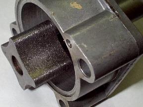 Full Size Picture (400k)
Enlosed find a picture why you might encounter a sudden drop of
your oil pressure. This oil pump already sucked some metal
parts in. Oil pressure when cold is almost the same, with hot oil
you're down to 0.5 bar ( psi).
Btw. examination of the engine
showed no damage to the crankshaft bearings or camshaft... so the oil filter
does what it is supposed to do (at least for a period of time)
Tom
Additional Comments (by Mike Wattam, Triumph Stag Register)
The best thing about oil gauges is, the Stag doesn't normally have one!
I don't, because:
- they are something else to worry about
- they are never accurate
- oil pressure is of hardly any consequence
- They don't measure oil flow
- oil pressure is controlled by the relief valve, more than the bearings
It is possible to have very high oil pressure but no oil flow through the bearings, leading to failure.
Conversely, nil oil pressure may mean there is plenty of oil going through
the (sloppy but not failed) bearings.
If the bearings are worn out, you'll hear them. Because the camshaft
chambers are fed by oil bled from the main bearings, if the bearings are
worn out the camshafts don't get fed oil, so noise rapidly develops.
I can more or less guaranteee that if you take off the oil pump and strip
out the pressure relief valve, you will find it is not correctly or fully
seated in the housing, and has badly worn on one side. This causes poor
oil pressure idling when hot in particular and has caused many to strip
their Stags unnecessarily, rebuilt with new bearings and then found no
change in the oil pressure.
The spring used in later Stag oil pump relief valves is a terrible design
with about one third of its length being coil-bound. It helps the valve
stick in its housing and has almost no movement, the spring rate is also
very high. Re-engineered springs give a good consistent oil pressure at
all engine speeds and the valve does not stick.
So, what I am saying is don't worry about the oil pressure unless you have
other symptoms. If you must still worry, look at the oil pump pressure relief valve.
Mike Wattam
Triumph Stag Register
Tires Sizes (by Brian Tink, 73 Stag)
A Michelin dealer gave me the following details regarding rolling circumference.
Standard 175    * 14  =  634 millimetres

         185/70 * 14  =  616

         195/75 * 14  =  630
So it would seem that the 195's are the closest to the 175 originals, with
only a 0.63% negative difference, whereas the 185 have a 2.99% negative difference
[SOL Home Page],
[Euro Clubs Page],
[Triumph Home Pages]
These pages are maintained by Tom Jell
Please send comments, additions, & errors to jell
Copyright © 1995-99 Jell,Radlhammer
 Full Size Picture (400k)