I have doodled up a schematic for what I think could be a wheel slip meter.
It is a conbination of three circuits from some old Radio Shack books by
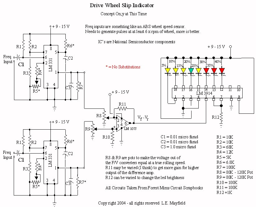
Forest Mims. The first section on the left is the frequency to voltage
converter. The frequency needs to come from sensors which will generate
around 6 - 10 times the rpm of the wheel at some nominal speed. There are 2
of these doohickeys one for a driven wheel and one for undriven. The op amp
in the second part is to take the difference of the outputs from the F/V
converters. This is where the slip is determined. 2 pots are used to make
the outputs the same when traveling at no slip speed. The gain resistor can
I think be changed to increase the voltage output if needed and it probably
will be. The bar graph generator wis used to display the amount of slip in
increments. Yellow is wasting speed, green is good, red is wasting tires.
Only 12 resistors, 2 caps, 1 voltage source, 2 IC's. Simple if it will work.
Hear that? I have not built this yet, so you are on your own. I plan to
build one over the next couple of months if things go right.
Here is the link http://www.mayfco.com/slipmtr.jpg
I would appreciate it if one of you electronics weenies would look at this
and tell me where I am full of it (which is likely to be everywhere as I am
less than ignorant of electronics).
I also believe this could be done really quickly using some sort of tiny
basic postage stamp computer reading the digital input, converting to freq,
doing the math and outputting a signal to some sort of meter. This migh
teven be better than the above. Let's hear it from some of you others who
are REALLY smart on this stuff...
mayf. out in Pahrump, cold and sorta dreary
|