 Technical Archives
 Technical Archives
This page was last updated on $Date: 1999/01/07 01:55:35 $.
These are the notes I've made from taking a few HF.1748 horns apart. This particular horn is found on the Austin-Healey 100, 100-6 and 3000s up til the introduction of the BJ-7.
I'm not an expert, so please don't take what I write as gospel. Refurbished horns are available for $100 each and that's probably not a bad price if your horns are in rough shape. I haven't seen anything published about the horns beyond adjustmenting them and I was curious about what was inside them. As the horns are assembled with screws and nuts, it would seem that I should be able to take several apart and get at least one back together....
As I try to get a horn back together I'll update this article. Hopefully, I be able to wake the neighbors!
A pair of horns are installed, one low tone and one high tone. On the 100, the horns are installed on the front crossmember in front of the radiator. For the 100-6 and 3000 roadster, the horns were attached to the cowl and cross-brace assembly just to the outside of the heater and fresh air intakes.
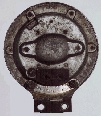
Each horn has an id tag installed on the back side the horn using the same cheese head screws for attaching the mounting bracket. Information on the tag include the model number, the voltage, and the month and year of manufacturing.
| Front Side | Back Side |
|---|---|
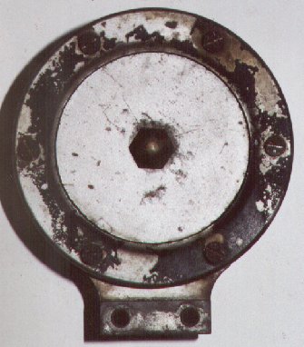 |
 |
The diaphram of the low tone horn is painted gloss black and may have one vee notch on the outer edge. The diaphram of the high tone horn is the same metallic biege as the rest of the horn and may have two vee notches on the outer edge.
Note: the size of the threads found in the brass nut, the thin nut and the threaded tube appears to be 13/32"-40 tpi. A pretty odd size.
The inside of the horn should look something like this:
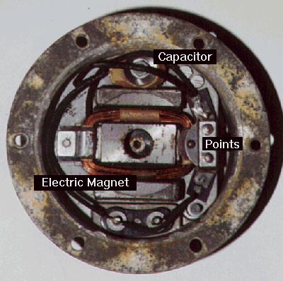
The electrical components consist of a electric magnet, a set of points, and a capacitor. The coil for the electric magnet is made of 460 inches of 22 B&S gage ( 0.0254 inch dia. ) enameled magnet wire. The capacitor has a value of 0.1 microfarrads and is wired across the points to reduce arcing when the points are opened.
The ring may have the word LUCAS cast in. LUCAS should be located 180 degrees from the mounting bracket.
Please send comments, additions, and errors for the SOL Healey web pages to Bob Haskell.
[SOL
![]() Web
][
Scions of Lucas
Web
][
Scions of Lucas
![]() Home Page
][
SOL British Car Clubs Page
]
Home Page
][
SOL British Car Clubs Page
]