 Technical Archives
 Technical Archives
This page was last updated on $Date: 1999/01/07 01:51:01 $.
As is the case with most of the mechanical components of the Healey, the overdrive unit is of very heavy-duty construction and certainly up to the task demanded of it, given reasonable care. At least annually, drain the transmission and overdrive units and refill with non-detergent oil if available. Note that there is a drain on both units, although they share a common oil supply. A filter is incorporated in the drain assembly of the overdrive unit, and should be cleaned at this time. Depending on the model, there may be a series of magnetic rings below the filter to catch metal particles and these should be thoroughly cleaned before replacing the drain and filter. The capacity of the transmission and overdrive oil sump is 3.75 US quarts. The overdrive unit will retain approximately 1/6 of a quart after draining, so fill with about 3.6 quarts. On center shift models, a dip stick is incorporated with the fill plug, so after refilling, drive around the block and recheck the level.
The majority of problems experienced with the overdrive unit are electrical in nature. This is especially true if the unit will not engage. Fortunately, the electrical circuit is pretty simple, consisting of only 5 components. These are:
The letters, A, B, C, E, and F correspond to the accompanying diagram, stolen from the Bentley manual.
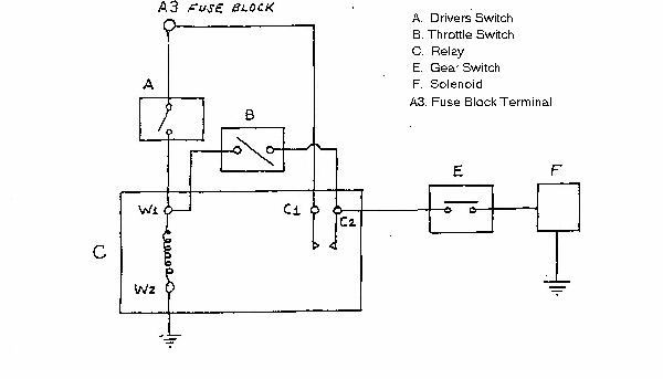
The operation is as follows. Turning on the drivers switch (A) energizes the relay (C) and applies voltage to both the throttle switch (B) and the gear switch (E). Lets ignore the throttle switch (B) for a moment, and go on to the gear switch (E). The gear switch has only one purpose in life; to make sure the transmission is in either 3rd or 4th gear before allowing the overdrive unit to engage. If this is the case, the solenoid will energize, moving a lever which opens the hydraulic operating valve inside the overdrive unit. Thats all there is to engaging overdrive. But what about the throttle switch we ignored? It is part of a self-holding circuit for the relay. It's purpose is to not allow the overdrive to dis-engage under a deceleration condition which would cause a shock load to be felt by the transmission. When you turn off the drivers switch, the overdrive should not disengage unless the throttle is at least 1/5 open, if the throttle switch is properly,adjusted. That, my friends, is all there is to the entire system.
You will need a voltmeter and have the transmission tunnel removed.
There are 2 adjustments to the electrical circuit; the throttle switch opening position, and the solenoid lever position.
First, the throttle switch. If an adjustment is required, loosen the clamp nut on the lever on the side of the throttle switch. Move the throttle linkage to the 1/5 open position and block it. While measuring the ohms across the throttle switch (again, with everything turned off!), place a screwdriver in the slot cut into the end of the throttle switch shaft and rotate slowly until the it is right at the point of the meter trying to make up its mind which way to go. Carefully lock the nut on the clamp and remove whatever you blocked the linkage with. Remove the meter.
Secondly, the solenoid lever. Locate the alignment lever on the opposite side of the overdrive unit. This lever is attached to the shaft which passes straight through the overdrive from the solenoid lever. The other end of the alignment lever has a 3/16" hole drilled in it. This hole should line up perfectly with the 3/16" hole behind it on the overdrive housing. (note: if there are 2 holes in the housing, use the top one). If adjustment is required, loosen the clamp bolt on the solenoid lever and move the alignment lever until a 3/16" rod will pass through the hole in the lever and into the hole in the housing. With the solenoid energized, lock the clamp bolt and remove the rod from the alignment lever.
If the electrical system checks out, and the adjustments have been set properly, the overdrive unit will probably function satisfactorily. If not, first rent a porta-crane....
Turn on ignition, O/D dash switch and have car in 4th gear.
To check operation of throttle switch:
Ignition switch on, car in 4th gear, flip on O/D dash switch. Solenoid should energize (audibly detectable), if not go back to top of this sheet! If it does, turn off O/D dash switch while placing no pressure on gas pedal. Solenoid should not de-energize. Now slowly depress gas pedal. At about 1/5 throttle, solenoid should de-energize. If so proceed to step 1 (Overdrive works fine), if not refer to throttle switch check-out and adjustment in the text.
Please send comments, additions, and errors for the SOL Healey web pages to Bob Haskell.
[SOL
![]() Web
][
Scions of Lucas
Web
][
Scions of Lucas
![]() Home Page
][
SOL British Car Clubs Page
]
Home Page
][
SOL British Car Clubs Page
]